Testing a diode may seem like a small task, but it’s a vital skill in electronics. Diodes are everywhere — inside chargers, TVs, radios, power supplies, and even your phone’s motherboard. If a diode fails, the circuit can stop working, or worse, get damaged. The good news is, you don’t need expensive tools to check if a diode is good or bad. A simple multimeter is all you need. But using it correctly, and knowing what the results mean, can be confusing for beginners. In this guide, you’ll learn not just the basic steps, but also the reasons behind each step, practical tips, and common mistakes to avoid. By the end, you’ll feel confident testing diodes with a multimeter — whether you’re fixing a gadget, building a project, or just learning electronics.
What Is A Diode And Why Test It?
A diode is a small electronic part that allows current to flow in only one direction. Think of it as a one-way street for electricity. The most common type is the silicon diode, but there are also LEDs, Zener diodes, and Schottky diodes, each with their own special uses.
When a diode fails, it can become open (no current flows at all), shorted (current flows both ways), or leaky (some current sneaks through in the wrong direction). A failed diode can cause all kinds of issues, like:
- Power supplies that won’t turn on
- Flickering or dead LEDs
- Audio equipment with strange noises
- Circuits that behave unpredictably
Testing diodes is important because it helps you quickly find and replace faulty parts, saving time and money.
Tools Needed To Test A Diode
To test a diode, you need a few basic tools:
- Digital Multimeter (DMM) – This is the main tool. It should have a “Diode Test” mode, but if not, you can use the resistance (ohms) setting.
- Analog Multimeter (optional) – Some older meters can test diodes too, but the method is a little different.
- Test Leads – These connect your multimeter to the diode.
- Tweezers or Small Pliers (optional) – Useful for handling small diodes.
- Soldering Iron (optional) – For removing diodes from a circuit board if necessary.
If you’re just starting, a basic digital multimeter is enough. Most multimeters today, even cheap ones, include a diode mode.
Understanding Diode Polarity And Symbols
Before testing, it’s important to understand the polarity of a diode. A diode has two ends:
- Anode (positive side)
- Cathode (negative side)
On the physical diode, the cathode is usually marked with a stripe. On circuit diagrams, the symbol looks like an arrow pointing towards a line:
- The arrow is the anode
- The line is the cathode
This is important because current should flow from anode to cathode, but not the other way.
How Does A Multimeter Test A Diode?
A digital multimeter in diode mode applies a small voltage (usually about 2V) across the diode and measures how much voltage is dropped across it. If the diode is good, it will show a voltage drop when connected in the forward direction, and almost nothing (or “OL” for overload/open loop) in the reverse direction.
A silicon diode typically shows a voltage drop of 0.6 to 0.7 volts in the forward direction. Other diodes, like Schottky or LEDs, have different values.
If you use the resistance (ohms) mode, the meter sends a smaller voltage, so the readings are less accurate and can be confusing. Whenever possible, use diode mode.
Step-by-step Guide: Testing A Diode With A Digital Multimeter
Let’s walk through the exact steps for testing a diode. This process works for most common diodes.
1. Power Off The Circuit
Always turn off and unplug the device before testing diodes inside it. Testing a live circuit can give false readings or damage your multimeter.
2. Locate The Diode
Find the diode on your circuit or take the loose diode you want to test. Note the stripe marking the cathode.
3. Remove The Diode (if Necessary)
You can often test diodes while they’re still in the circuit. But, if you get strange readings, or there are other components connected in parallel, you may need to desolder one leg of the diode. This ensures you’re only testing the diode, not the rest of the circuit.
4. Set The Multimeter To Diode Test Mode
Turn the dial to the diode symbol (usually a triangle with a line). The meter is now ready to test.
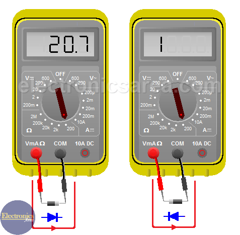
5. Connect The Test Leads
- Red lead to the anode (non-striped side)
- Black lead to the cathode (striped side)
This is the forward bias direction.
6. Read The Display
A good silicon diode will show 0.6V to 0.7V (the forward voltage drop). If the reading is outside this range, the diode may be faulty or not a silicon type.
7. Reverse The Leads
Swap the leads:
- Red lead to the cathode (striped side)
- Black lead to the anode (non-striped side)
This is the reverse bias direction.
8. Read The Display Again
A good diode should show OL (open loop), “1”, or a very high number. This means no current is flowing in reverse, as expected.
9. Interpret The Results
Here’s a quick summary in a simple comparison:
| Test Condition | Expected Reading | What It Means |
|---|---|---|
| Forward Bias (Red to Anode, Black to Cathode) | 0.6V–0.7V | Diode is Good |
| Reverse Bias (Red to Cathode, Black to Anode) | OL (Open Loop) | Diode is Good |
| Both Directions | OL (Open Loop) | Diode is Open (Bad) |
| Both Directions | 0V or Very Low | Diode is Shorted (Bad) |
If you see readings outside these patterns, double-check your connections and try removing the diode from the circuit.
Testing Diodes Using Resistance (ohms) Mode
Some multimeters lack a diode test mode. In this case, use the resistance (ohms) setting. The process is similar, but the numbers are different.
- Set the meter to the lowest ohms range.
- Connect the leads as before.
- In forward bias, you should see a low resistance (a few hundred to a few thousand ohms).
- In reverse bias, you should see a very high resistance (often over 1 megaohm).
This method is less precise, and not all meters supply enough voltage to forward bias all diodes. But it’s better than nothing.
Special Cases: Testing Different Types Of Diodes
Not all diodes behave the same way. Here’s how to test some common special types.
Light Emitting Diodes (leds)
LEDs are diodes that light up when current flows through them. Their forward voltage drop is usually higher than silicon diodes.
- Forward voltage is typically 1.8V to 3.3V, depending on color and type.
- Some multimeters can light up the LED faintly in diode mode.
- If your meter shows “OL” both ways, try a different meter or use a simple battery circuit to test.
Zener Diodes
Zener diodes conduct in reverse at their breakdown voltage (e.g., 5.1V, 12V). In normal diode test mode, they behave like regular diodes.
- Test as with a regular diode.
- The reverse breakdown can’t be tested with a multimeter; you need a special setup.
Schottky Diodes
Schottky diodes have a lower forward voltage drop, typically 0.2V to 0.4V.
- In diode mode, a reading in this range is normal.
- If you see 0.6V or higher, check if it’s really a Schottky type.
Germanium Diodes
Older germanium diodes have a forward voltage of 0.2V to 0.3V.
- Don’t mistake a low reading for a shorted diode.
- Know your diode type before judging the result.
Here’s a table summarizing typical forward voltage drops:
| Diode Type | Forward Voltage (V) | Comments |
|---|---|---|
| Silicon | 0.6 – 0.7 | Most common |
| Schottky | 0.2 – 0.4 | Fast switching |
| Germanium | 0.2 – 0.3 | Vintage, audio circuits |
| LED | 1.8 – 3.3 | Depends on color |
| Zener | 0.6 – 0.7 (forward) | Acts like silicon in forward mode |
Testing Diodes In-circuit Vs. Out-of-circuit
Testing a diode in-circuit (without removing it) is faster, but other components can affect your readings. For example, parallel resistors or capacitors might show a false short or leakage.
- If you get a confusing reading, remove one leg of the diode from the board and test again.
- Sometimes, you can compare with a known good diode in the same circuit for reference.
Common Mistakes When Testing Diodes
Even experienced people can make errors when testing diodes. Avoid these common pitfalls:
- Testing in a live circuit – This can damage your meter or give false readings.
- Not identifying the cathode/anode – Make sure you know which end is which.
- Ignoring the diode type – Remember, forward voltage varies by type.
- Trusting only one test – If you’re unsure, test in both directions and compare.
- Forgetting about parallel paths – Other components can “trick” your meter, so isolate the diode if needed.
- Using the wrong meter mode – Always use diode mode if available.
- Not checking meter battery – Low battery can give strange results.
Interpreting Multimeter Readings: Real Examples
Let’s look at some typical scenarios and what they mean.
Example 1: Good Silicon Diode
- Forward bias: 0.65V
- Reverse bias: OL
This is a normal reading for a working diode.
Example 2: Shorted Diode
- Forward bias: 0.00V
- Reverse bias: 0.00V
A reading near zero both ways means the diode is shorted. Replace it.
Example 3: Open Diode
- Forward bias: OL
- Reverse bias: OL
No conduction in either direction means the diode is open. It’s bad.
Example 4: Leaky Diode
- Forward bias: 0.65V
- Reverse bias: 1.2V (not OL)
If you see a lower than expected resistance or voltage in reverse, the diode is “leaky” and should be replaced.
Tips For Accurate Diode Testing
- Clean the leads – Dirt or oxidation can affect readings. Use a pencil eraser or fine sandpaper.
- Don’t squeeze too hard – Pressing too hard on the diode can bend or damage it.
- Wait a moment – Some meters need a second to stabilize the reading.
- Compare with a known good diode – If you’re unsure, test a new diode for reference.
- Record your results – Keeping notes helps spot patterns and errors later.
When To Replace A Diode
Replace a diode if:
- It reads shorted or open.
- It shows leakage in reverse.
- The voltage drop is far outside the expected range.
- The circuit still doesn’t work after other checks.
A faulty diode can cause damage to other parts, so don’t ignore suspicious readings.
Additional Uses For Multimeter’s Diode Test Mode
The diode test mode can help with more than just diodes:
- Testing LEDs – Check if they light up.
- Checking transistor junctions – Many transistors are like two diodes back-to-back.
- Identifying diode polarity – Find the cathode/anode if the markings are missing.
- Testing continuity in small fuses – A good fuse behaves like a shorted diode.
How To Test Surface Mount Diodes
Surface mount diodes (SMDs) are tiny and harder to handle. Here’s how to test them:
- Use fine-point meter probes or test clips.
- Refer to the board’s markings to identify the anode/cathode.
- If needed, use tweezers to gently hold the diode.
- For hard-to-reach parts, consider using flexible leads.
Be careful not to slip and short nearby components.
Diode Testing: Analog Multimeter Vs Digital Multimeter
Some older analog meters can test diodes, but the method is different:
- Set the meter to a low resistance range (x1 or x10).
- Forward bias: The needle should move to a low resistance.
- Reverse bias: The needle should stay at a high resistance.
Analog meters can sometimes supply more current, which may damage sensitive diodes or LEDs. Always start with a digital meter if possible.
Here’s a quick comparison:
| Feature | Digital Multimeter | Analog Multimeter |
|---|---|---|
| Accuracy | High | Moderate |
| Diode Mode Available | Yes (usually) | No |
| Ease of Reading | Easy (digital display) | Requires interpretation (needle) |
| Risk of Damaging Sensitive Parts | Low | Medium |
Non-obvious Insights For Beginners
- Not All Multimeters Can Test All Diodes: Some cheap multimeters can’t supply enough voltage in diode mode to properly test high-voltage LEDs or certain Zener diodes. If your meter shows “OL” both ways on an LED, try a different meter or a simple test circuit with a resistor and battery.
- Testing in Circuit Can Fool You: When a diode is still connected to other components, your reading may not make sense. For example, a capacitor in parallel can charge and show a false “short.” If in doubt, always lift one end of the diode from the board.
Safe Handling And Precautions
- Static electricity can damage sensitive diodes, especially Schottky and signal diodes. Ground yourself before handling.
- Do not force the probes into tight spaces; you may slip and cause a short.
- After soldering, allow the diode to cool before testing. Heat can temporarily change the reading.
Where To Learn More
If you want to dive deeper into diode types, testing, and theory, visit the Wikipedia Diode Article. It covers the physics, types, and uses in detail.

Frequently Asked Questions
What Does “ol” Mean On My Multimeter During Diode Test?
OL stands for “open loop” or “over limit.” It means the diode is not conducting in that direction — usually a good sign in reverse bias. If you see OL in both directions, the diode is open (bad).
Can I Test Diodes Without Removing Them From The Circuit?
Yes, but other parts in the circuit may affect your readings. If the result seems strange, desolder one end of the diode to isolate it.
What Is The Normal Voltage Drop For An Led In Diode Test Mode?
It depends on the color and type. Red LEDs are often around 1. 8V, while blue and white LEDs can be 3V or more. Some multimeters may not show a reading or light up the LED at all.
Is It Possible To Test Zener Diodes With A Multimeter?
You can test a Zener diode like a regular diode in forward mode. But to test its breakdown voltage (reverse mode), you need a circuit that applies a voltage higher than the Zener value.
What If My Meter Does Not Have A Diode Test Mode?
Use the lowest ohms (resistance) setting. You’ll see a low resistance in forward and high resistance in reverse for a good diode. However, this method is less accurate, especially for LEDs and Zener diodes.
Testing diodes with a multimeter is a simple but powerful skill in electronics. With practice, you’ll quickly spot bad parts and feel more confident troubleshooting devices. Remember to double-check your results, handle diodes with care, and always be safe when working with circuits.